
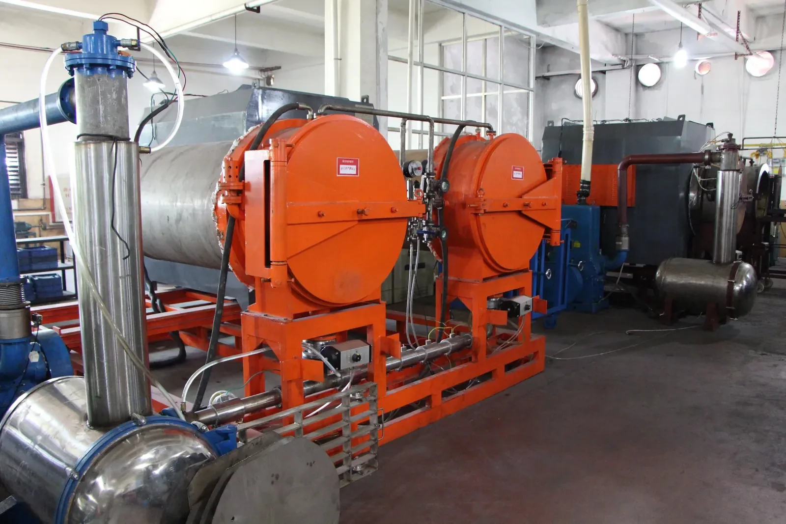
A metal injection molded component leaves the tool larger than the drawing requires. Nothing has gone wrong: the green part is dimensioned for the size it will reach after densification, not the size it has when it is ejected.
That single fact explains why shrinkage keeps returning to the drawing review. A part can be geometrically correct in the cavity and still miss its requirement in the furnace, and a percentage taken from a data sheet says nothing about whether the number was established for this material, this geometry and this cycle. This guide covers where the change comes from, why a percentage is not a scale factor, and how size is established and verified in practice.
Why do MIM parts shrink?
MIM begins with fine metal powder compounded with a binder system. The binder lets the mixture flow into the cavity and hold its shape after ejection; the molded component is called a green part.
Debinding removes most of the binder and leaves a porous skeleton that can still be handled and taken through the next stage. During sintering the remaining binder is removed, the metal particles bond, and pore space between them is eliminated. The component becomes denser — and because the same mass now occupies less volume, it becomes smaller. [1]
The large dimensional change therefore belongs to densification during sintering. It is a different effect from the ordinary thermal contraction a hot metal part shows while it cools: that happens to every metal part and is small compared with the densification step.
Because the change comes from pore removal rather than from a tool position, its magnitude follows the material system, the feedstock, the molding, the debinding and the sintering cycle. It is not a single setting that can be dialled to a number on a data sheet.
A 20% reduction is not a 20% enlargement
The arithmetic causes more confusion than the metallurgy. Linear shrinkage is quoted against the molded dimension, so a part that must finish at 10.00 mm with an assumed 20% linear shrinkage needs a green dimension of 10.00 / (1 − 0.20) = 12.50 mm.
Multiplying instead — 10.00 × 1.20 = 12.00 mm — produces a part that would shrink to 9.60 mm. On a 10 mm feature the error is 0.40 mm, well beyond any tolerance such a feature would carry.
| Finished dimension | Green dimension at 20% shrinkage | If enlarged ×1.2: green → result |
|---|---|---|
| 5.00 mm | 6.25 mm | 6.00 mm → 4.80 mm |
| 10.00 mm | 12.50 mm | 12.00 mm → 9.60 mm |
| 20.00 mm | 25.00 mm | 24.00 mm → 19.20 mm |
| 40.00 mm | 50.00 mm | 48.00 mm → 38.40 mm |
The figures show the direction of an error, not a shrinkage value. Compensation for a real tool is established for the selected material system and the planned cycle, then validated on measured parts.
Why a scale factor is not enough
A single factor describes a uniform change in size. On its own it cannot correct bending, twisting, ovality or a local change in shape — scaling the cavity makes the part uniformly larger without making it more correct.
The contributors to repeatability sit across the whole chain. Elnik Systems lists feedstock consistency, mold and setter design, molding, debinding, sintering and quality assurance among them, which is another way of saying that a dimensional problem found after sintering may have started well before the furnace. [2]
Geometry belongs in the same review. MIMA's design guidance recommends gradual transitions between different wall thicknesses and considers how a component can be supported during sintering. [3] Those are tooling and design decisions, and they are settled before the cavity is cut.
How size is actually controlled
Compensation is the applied correction, not the shrinkage figure. The cavity is dimensioned so that the molded component — after its specific debinding and sintering cycle — lands on the drawing. The value is established for the chosen material system and the planned cycle, and the relationship between the tool cavity, the molded component and the sintered result has to be treated as one system.
In practice this is a loop rather than a calculation: adjust the tool, mold, debind, sinter, measure against the agreed datums and method, compare with the requirement, correct. How many passes a part needs depends on how far the first result sits from the requirement, and on how much of the variation is systematic — attributable to the tool — rather than run-to-run variation from feedstock and furnace.
Two consequences follow for the buyer. The same drawing in a different alloy can need a different compensation, so a shrinkage percentage carried over from another project is not evidence. And a quotation that offers a shrinkage number without a route for confirming it is missing the part that actually delivers the dimension.
Read the part through its interfaces
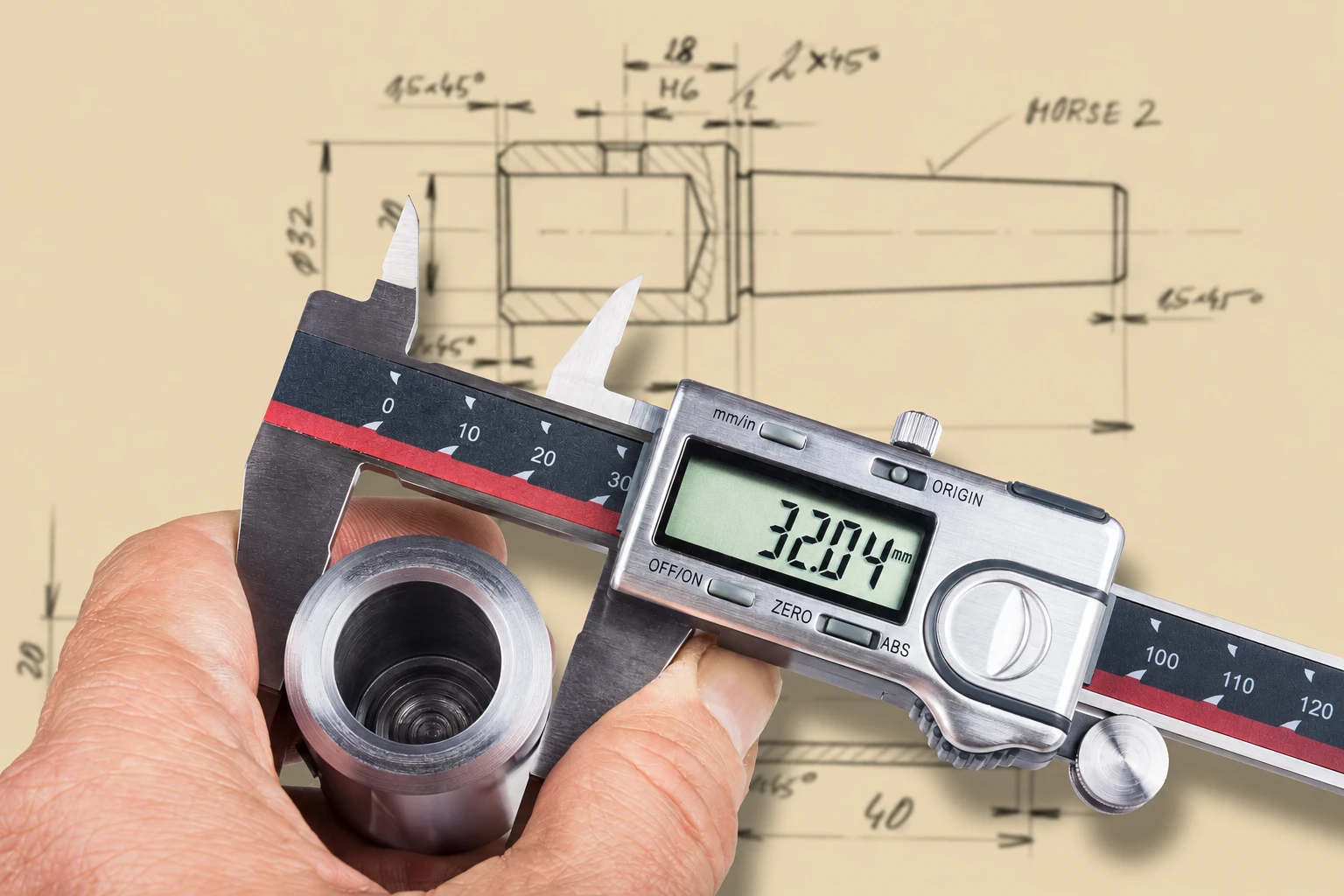
Picture a small lock component with a central bore, a raised boss and features at either end of the body.
If the bore locates a pivot, its diameter is only one part of the requirement. The relationship between the bore axis, the surrounding face and the end features may be what decides how the mechanism moves. That produces several different questions, and they do not all have the same answer:
- Can the overall body remain as-sintered?
- Does the bore require a finishing operation?
- Which features establish the inspection datums?
- Must the final dimensions be checked after heat treatment or surface finishing?
These are questions for the drawing and the application. A photograph cannot establish the required fit, the loading or the tolerance.
Where secondary operations fit
MIM produces a near-net-shape component; it does not require every surface to be accepted directly from the furnace. Sizing, machining, heat treatment and other operations can be included where the final requirement calls for them. [1]
The useful distinction is between geometry that the molding-and-sintering route can deliver and interfaces that need an additional operation to be controlled. Applying the tightest tolerance to every feature blurs that distinction, and it usually raises cost without improving the part.
A clear starting point for review is to mark the functional dimensions, their datums and the condition in which each must be met. The route can then be assessed against those requirements instead of against a general tolerance block. Compare the options side by side in the MIM vs. CNC drawing review checklist.
What to put on the drawing
The list below is short, but it removes most of the ambiguity a shrinkage discussion otherwise creates.
| Item | What to state |
|---|---|
| Function | What the feature does in the assembly, and what it mates with. |
| Functional dimensions | The bores, faces and fits that carry the requirement — marked on the drawing, not implied by a general note. |
| Datums | Which faces or axes establish inspection, and in which condition they apply. |
| Condition | As-sintered, after sizing, after machining, after heat treatment or after coating. |
| Material system | Grade and final condition, so compensation and the sintering window are set for the right material. |
| Inspection | Method and sampling agreed for the marked features before the first parts are measured. |
| Volume and cadence | Annual demand and call-off pattern, because they decide whether tooling and finishing are planned as a fixed or a flexible route. |
Shrinkage is expected. The engineering task is to make it repeatable, to understand where the shape changes as well as the size, and to plan how the final interfaces will be reached.
Conclusion
Shrinkage is not a defect to be argued away. It is the mechanism by which the part gains its density, and it is why metal injection molding can produce small, complex geometry at production volumes.
A part dimensioned through its interfaces — functional features, datums and required condition stated — gives both sides something to check. The number in the furnace then becomes a controlled variable rather than a surprise discovered at first article.
Related component families
These pages apply the same review to specific component types.
Mechanism Components
Bores, bosses and locating features that usually decide the finishing plan.
Component guide →Shafts, Pins and Plungers
Where journals and straightness typically need a pass after sintering.
Component guide →Component Design Notes
DFM notes by feature type, from wall sections to holes and radii.
Component guide →Have a drawing to discuss?
Send it to our engineering team. We review process fit and identify the information needed for a quotation.
Send Drawing for Review