
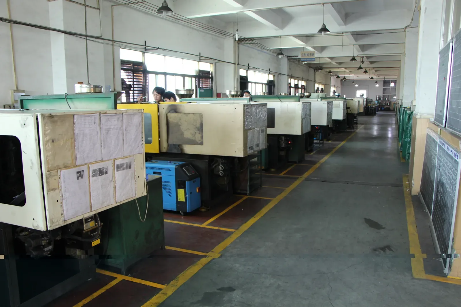
Metal injection molding (MIM) makes small, geometrically complex metal parts by moulding a mixture of fine metal powder and a polymer binder into shape, removing the binder, and sintering the remaining powder into a dense solid. The shape comes from a mould, the material properties come from the metal, and the two halves of that sentence are equally important.
Buyers usually arrive at MIM from one of two directions: a machined part whose cost or lead time has become painful, or a design that cannot be produced at all by stamping, casting or conventional powder metallurgy. This guide covers what each stage of the process actually does, which tolerances survive sintering, which failure modes show up late, and how to screen a part in a few minutes.
What MIM actually is
Start with the material, because that is where most misunderstandings begin. MIM feedstock is not metal dust held together by glue. It is a carefully compounded mixture in which fine spherical metal powder — usually produced by gas atomisation with a median particle size around 8–12 µm — is coated and suspended in a thermoplastic binder system. The powder makes up roughly 60% of the volume. That number matters: if the powder loading is too low, the part shrinks excessively and distorts; if it is too high, the feedstock becomes too viscous to fill a thin cavity.
The mould does for metal what it does for plastic: it defines the shape. Everything after moulding exists to remove the binder and weld the powder particles into a solid. Debinding opens up the pore channels, and sintering closes them, pulling the particles together until the part is dense. The part that comes out of the furnace is a real metal component with its own grain structure, mechanical properties and heat-treatment response.
The practical consequence is that MIM is a forming route. Its competitor is not "cheap metal" — it is a sequence of machining operations, a casting, or several stamped pieces welded together. Compare it against that whole stack, not against a raw material price.
The six stages, in practice
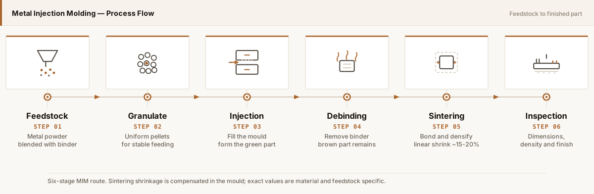
Suppliers use different equipment and different process windows, but the sequence is consistent. Here is what happens at each stage and which parameter usually decides whether the part comes out right.
1. Feedstock preparation
Metal powder is mixed with the binder system and compounded into pellets. The powder choice fixes the material properties later; the binder choice fixes how the feedstock flows. Common systems are wax-polymer, catalytic (polyacetal-based) and water-soluble. This stage is where magnetic properties, corrosion resistance and heat-treat response are effectively locked in, because they are functions of alloy composition and carbon content — both of which are difficult to adjust after sintering.
2. Injection moulding
The feedstock is heated and injected into a steel mould, producing the green part. Green parts carry the full intended geometry, including small holes, slots and textured surfaces, and they are dimensionally close to — but noticeably larger than — the finished part, because shrinkage has not happened yet. Tooling design at this stage must already compensate for the shrinkage that comes later.
3. Debinding
The binder is removed thermally, by solvent, catalytically, or by a combination. The result is the brown part: a fragile, porous object that is mostly metal powder with open channels where the binder used to be. Brown parts break easily, and process control here is unforgiving. Incomplete debinding traps carbon and leaves defects; overly aggressive debinding damages the part before sintering can strengthen it.
4. Sintering
The brown part is heated to 1,250–1,380 °C for stainless steels — below the melting point of the alloy — in a vacuum or controlled atmosphere furnace. Particles bond by diffusion, the pores close, and the part densifies to 95–99% of theoretical density. This is where the part gains its mechanical properties, and it is also where the linear shrinkage of 15–20% occurs. Shrinkage is predictable within a material system but sensitive to powder lot, binder content, furnace profile and part mass.
The single most expensive misunderstanding in MIM: treating shrinkage as a fixed percentage. It is a process characteristic that must be characterised for the specific feedstock, part geometry and furnace load, then verified on first articles. A supplier who quotes tight tolerances without discussing shrinkage characterisation is quoting a hope, not a capability.
5. Secondary operations
Near-net-shape is not net-shape. Depending on the drawing, parts may need de-burring, machining of critical bores or threads, heat treatment, tumbling, passivation, plating or PVD coating. A useful rule when reading a drawing: any feature whose tolerance is tighter than about ±0.1% of its dimension is probably a machining feature, not a moulding feature.
6. Inspection and qualification
Final inspection covers dimensions, density, hardness, appearance and any application-specific requirement. Density is normally measured by the Archimedes method and reported as a percentage of theoretical density; it is a good early indicator of a furnace problem. For export OEM programs, dimensional capability across a production run matters far more than the beauty of the first sample.
Where MIM wins and where it stops
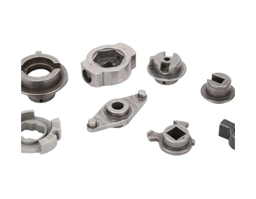
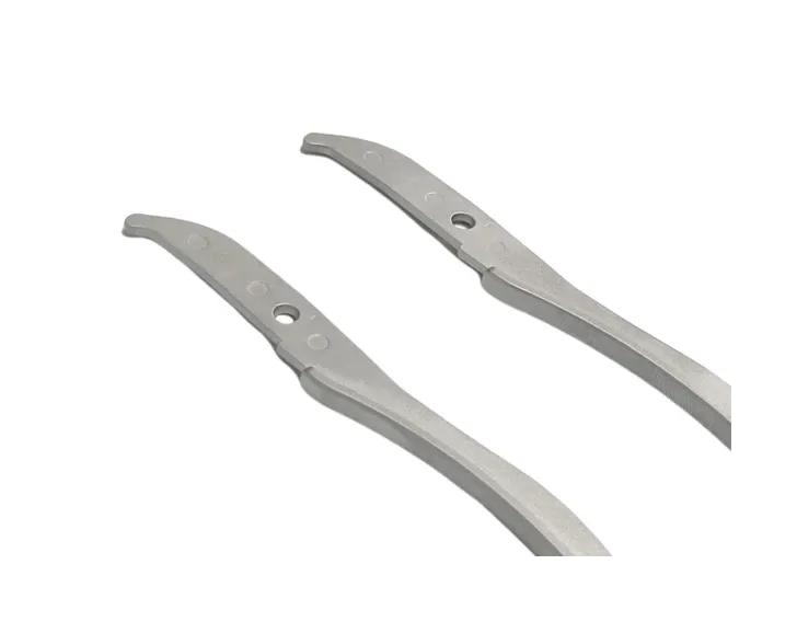
MIM has a real but bounded territory. The boundary is set by geometry, mass and volume — in that order.
| Condition | MIM is a strong fit | Another route is usually better |
|---|---|---|
| Geometry | Three-dimensional features, side holes, undercuts, thin walls, internal detail | Simple rotational or prismatic parts — turning and milling are faster |
| Part mass | Roughly 0.5–100 g | Very small parts favour PM; large parts favour casting or machining |
| Wall section | About 1–3 mm, reasonably uniform | Very thick sections, or ratios above roughly 3:1, invite voids and distortion |
| Annual volume | Enough to amortise a mould and a sintering setup | Prototype and low-volume runs — no tooling is required for machining |
| Tolerance | ±0.3–0.5% as-sintered on general dimensions | Tolerances tighter than roughly ±0.05 mm on many features |
| Material | Stainless steels, low-alloy steels, soft-magnetic alloys, titanium, tungsten | Alloys that cannot be atomised or sintered in the required composition |
Failure modes that surface late
Most MIM programs that disappoint do so for reasons visible on the drawing long before the first part is made. These are the five that recur.
- Uneven wall sections. Thick masses sinter more slowly than thin walls. Where a heavy boss meets a 1 mm wall, the thick section stays porous while the thin one is fully dense, and the difference shows up as sink, warpage or a density gradient. Keeping section ratios below roughly 3:1 avoids most of it.
- Distortion on long, flat or slender parts. Shrinkage is not perfectly isotropic, and gravity acts on a soft brown part at high temperature. Long thin parts and large flat faces need support design or a different process.
- Assuming a tolerance percentage is an absolute number. "±0.3%" on a 5 mm feature is ±0.015 mm — roughly a machining tolerance, not an as-sintered one. The same percentage on a 60 mm dimension is ±0.18 mm, which is comfortable. Read the drawing feature by feature.
- Internal porosity discovered at polishing. A part can pass dimensional inspection and still reveal subsurface pores when a cosmetic surface is buffed. If appearance matters, say so at RFQ stage so density and process control can be tightened.
- Tooling that never amortises. MIM tooling is a real investment. If annual demand is modest or the program life is short, the honest recommendation is often to keep machining until volume justifies the mould.
How to screen your part in five minutes
Before contacting any supplier, run the drawing through these questions. A "yes" to most of them means MIM is worth a proper quote.
- Is the part small — roughly palm-sized or smaller — and reasonably light?
- Does it have genuinely three-dimensional features that would need multiple machining setups?
- Would producing it by machining remove a large share of the raw material as chips?
- Is the wall section between roughly 1 mm and 3 mm, without extreme thick-to-thin transitions?
- Is there repeat annual demand, or a program life long enough to absorb tooling?
- Are the tightest tolerances limited to a handful of features that could be machined after sintering?
If the answer to the last two questions is "no" and "few", MIM is likely to be competitive. If the part is a simple cylinder, a plate, or a one-off prototype, another process will almost certainly be cheaper.
Specifying material and tolerance
Two fields in a quotation request drive most of the technical outcome. Material selection determines whether the part can meet its mechanical, corrosion and magnetic requirements at all; tolerance structure determines how much secondary machining is priced into the unit cost.
For material, name the grade you need rather than a generic family. 316L is the most widely specified MIM stainless steel for corrosion resistance in general service. 17-4PH is used where strength and hardness matter, since it responds to precipitation hardening. Fe-Ni and Fe-Si alloys cover soft-magnetic applications. Titanium and tungsten alloys are available but are project materials — they need early discussion, not a line item on a standard quote.
For tolerance, mark only the features that matter functionally. A drawing that applies ±0.02 mm everywhere pushes the whole part into machining and destroys the economics MIM was chosen for. The better practice is to leave general dimensions at as-sintered tolerance and identify the specific fits, bores and datum surfaces that need a secondary operation.
What to send for a MIM quotation
A usable MIM quotation needs five things: a 2D drawing with tolerances, a 3D model where available, the material or its performance requirement, annual volume and expected program life, and a note on the application and any cosmetic or regulatory requirement. With those, a supplier can assess manufacturability, propose a process chain, and give a tooling and unit-cost structure that reflects reality.
Where MIM fits in SINTS programs
SINTS runs MIM and press-and-sinter powder metallurgy, and reviews parts against CNC, turning and casting rather than promoting one route. In practice MIM is proposed when a small component combines three-dimensional geometry, repeat volume and material requirements that machining cannot deliver economically. Application-specific examples sit in our guides for robotic grippers, robot tool changers, solenoids and micro fluid control, and dispensing and metering systems.
Related component families
These component-family pages move from general process guidance to drawing-specific DFM questions.
Mechanism Components
Compact links, levers, pawls, cams and feature-rich latches are common MIM screening candidates.
Component guide →Shafts, Pins and Plungers
MIM becomes relevant when shaft-like parts integrate non-axisymmetric features; critical journals may still be finished.
Component guide →Precision Small Components
Brackets, carriers, hinges and inserts can benefit from geometry consolidation at repeat volume.
Component guide →Fluid-Control and Dispensing
Valve-adjacent and plunger-type components where bore quality and repeatability drive the specification.
Component guide →Conclusion
MIM is a good process with a narrow address. It produces small, complex, three-dimensional metal parts in volume with material properties that come from real metallurgy, not from a binder. It charges for that in tooling, in shrinkage that must be engineered rather than assumed, and in a size and section range that excludes large or chunky parts.
The right way to evaluate it is to compare the complete route: what the part costs to make by MIM including secondary operations and tooling amortisation, against what it costs by machining, casting or assembly. That comparison, run on your actual drawing and volume, is worth more than any general statement about which process is "better".
Have a drawing to discuss?
Send it to our engineering team. We review process fit and identify the information needed for a quotation.
Send Drawing for Review