
2-jaw parallel grippers
Common architectures use wedges, rack-and-pinion sets, links or guided master jaws to synchronize two sides. Compact internal mechanism parts can be attractive MIM/PM candidates.
Wedges, cams, master jaws, guides, links, racks, pinions, pivots and locking parts can all be candidates for process review. The manufacturing route depends on load path, wear, precision, material, annual volume and which functional surfaces still need machining or grinding.
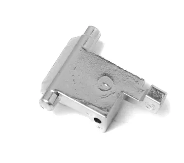
Manufacturing reference: Representative SINTS components are shown to illustrate linkage, shaft and compact mechanism geometries relevant to gripper engineering reviews. Final process selection is based on the actual drawing, material, tolerances, functional requirements and production volume.
A gripper can be simplified into six linked functions. Each function creates a different manufacturing problem — and that is what should drive the process choice.
Common architectures use wedges, rack-and-pinion sets, links or guided master jaws to synchronize two sides. Compact internal mechanism parts can be attractive MIM/PM candidates.
Self-centering systems often add multi-jaw synchronization, wedge hooks or gear-like elements. Wear, backlash and centering repeatability become more important.
Pivoting jaws create opportunities around small shafts, links, sector-like transmission parts and stops, while bearing or pivot surfaces may still need machining.
Longer guides and larger finger moments make stiffness, wear and synchronization more critical; some parts remain better suited to CNC or conventional gear processes.
Servo-driven designs can introduce small gears, screw-drive interfaces, levers, sensor targets and locking parts where repeatable high-volume metal production may matter.
Spring or mechanical holding systems can create small, highly loaded locking components. These are promising candidates only after strength, contact stress and cycle-life requirements are understood.
The table below is an initial screening tool. It is deliberately conditional: critical guide faces, gear quality, hard-contact surfaces and safety functions can change the final route.
| Component | Function | Likely first route to evaluate | Why / watchout |
|---|---|---|---|
| Wedge / cam | Converts actuator motion into jaw motion | MIM — high potential | Complex 3D form can favor MIM; contact faces, hardness and distortion need review. |
| Master jaw / base jaw | Guides motion and carries the external finger | MIM + machining, or CNC | Compact complex jaws may suit MIM, but guide surfaces, datums and stiffness can drive secondary machining. |
| Rack / pinion / small gear | Synchronizes opposing jaws | PM / MIM / gear process | Volume and geometry can favor PM or MIM; tooth accuracy, backlash and wear determine finishing needs. |
| Link / lever / pawl | Transfers motion or locks the mechanism | MIM — often worth evaluating | Good candidate when small, complex and repeated at volume; fatigue and bearing surfaces must be checked. |
| Guide / rail element | Controls straightness and moment load | CNC / grinding, sometimes MIM preform | Surface finish, hardness, straightness and running clearance are usually decisive. |
| Top jaw / custom finger | Directly contacts the workpiece | CNC often preferred | Frequently customized and lower-volume; MIM is not automatically economical. |
| Piston / simple shaft | Creates or transfers linear force | Turning / CNC often preferred | Simple rotational geometry normally does not need MIM unless other complexity changes the economics. |
| Housing / body | Contains guide, actuator and mounting features | CNC / casting / extrusion | Often too large or aluminum-based for MIM to be the natural first choice. |
SINTS component examples illustrate manufacturing geometry and process options. Final application suitability is assessed from your drawing and operating requirements.
Useful for discussing compact links, carriers, pivot features and integrated 3D geometry. Application, material and process fit still require drawing review.
SINTS manufacturing reference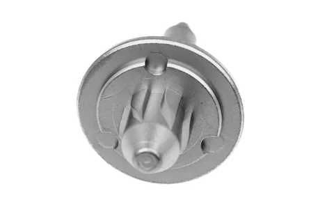
Useful for discussing rotational interfaces, integrated features and where turning, grinding or secondary machining may remain necessary.
SINTS manufacturing referenceUse the industry guide to understand load, wear and mechanism context. Use the Product family pages for component-level manufacturing logic.
Links, levers, pawls, cams, forks and locking elements.
Product family →Rack-and-pinion logic, compact gears, tooth accuracy, backlash and wear.
Product family →Pivots, spindles and moving interfaces where fit and secondary control matter.
Product family →Compact carriers, brackets, guides and interface parts.
Product family →Small complex 3D parts, multiple features that would otherwise need several machining operations, and repeat production volumes that can justify tooling.
Gears, bushings and structural parts whose geometry is compatible with pressing direction and where high repeat volume can benefit from near-net-shape production.
The part is low volume, frequently customized, large, simple to machine, or dominated by tight guide surfaces, bores and datum relationships that need direct machining.
Include critical dimensions, datums and any surfaces already known to require grinding or machining.
State the preferred grade, heat treatment, hardness and corrosion requirement if already defined.
Tooling economics can change completely between prototype quantities and stable serial production.
Separate functional tolerances from dimensions that are simply carried over from a machined design.
Maximum load, jaw moment, impact and contact direction help identify where strength and wear risk sit.
Repeated sliding, locking or gear contact needs a different review from a static structural part.
Cleanroom, washdown, food contact, dust, temperature or corrosive media can change material and surface-treatment choices.
If the part is already CNC-machined, share the current pain point: cost, capacity, consistency, part count or lead time.
Robotic grippers use small metal parts to open, close and sense — fingers, pivots, linkages, gears and guide components. These answers cover process selection for gripper parts and where CNC legitimately remains the better route.
Small complex wedges, cams, links, levers, pawls, compact base-jaw features and some locking parts are often worth evaluating first. Final suitability still depends on material, load, tolerance, wear and annual volume.
Not automatically. Top jaws and fingers are often customized and relatively low volume, so CNC can remain the better route. MIM becomes more interesting when geometry is complex and volume is stable enough to justify tooling.
Potentially. PM is a strong process to evaluate for repeat-volume gears and structural motion parts, but tooth geometry, density, strength, backlash, wear and finishing requirements determine whether it is suitable.
SINTS can provide an initial manufacturability and process-fit review from the drawing, material, annual volume and functional requirements. Strength, fatigue, safety functions and final tolerance commitments require project-specific engineering validation.
It covers the parts that convert an actuator input into a controlled grip — fingers and jaws, pivot pins and bushings, linkages and cam parts, gear and rack components, guide rails and the small mounting and adjustment hardware around them. The family spans electric, pneumatic and vacuum grippers, and the parts are typically small, load-bearing and produced in repeat volume once the gripper design is frozen.
Start at the load path rather than at the process. The gripping force passes from the actuator through the linkage or gear train to the finger contact, so the parts that carry that chain are sized by load, fatigue and deflection, while parts that only position or retain carry much less. That distinction usually shows that two or three components in the chain are the real candidates and the rest are not worth converting.
CNC remains the better answer when the finger is low volume, when it is a custom profilated part whose geometry changes per application, when it needs a specific surface finish or material that is not practical to sinter, or when the design is not yet frozen. Converting a low-volume custom finger to near-net shaping rarely pays back, and revision churn would make tooling a liability rather than an asset.
Send the drawing, the gripping force and any peak or impact load, the duty cycle, what the finger contacts and how hard it is, the required repeatability and clearance, the actuator type, the annual volume per variant and whether the design is frozen. Repeatability, clearance and contact hardness usually decide more at screening stage than a generic dimensional tolerance.
We can first look at geometry, material, volume, critical tolerances and likely secondary operations — including cases where staying with CNC is the better answer.