
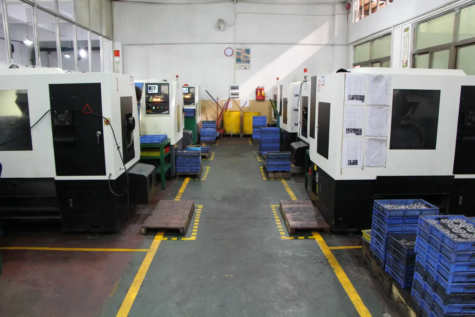
Route selection is usually framed as a preference: this supplier likes casting, that one likes machining. It is better framed as an elimination exercise. Each process has a hard boundary — a geometry it cannot form, a volume it cannot justify, a tolerance it cannot hold — and the boundaries do most of the deciding.
This guide covers the nine routes that account for the large majority of commercial metal parts, in the order a buyer is likely to consider them. For each one: what it does best, where it stops, and the signal that tells you to move on.
The nine routes at a glance
The table below compresses each route to the one sentence that usually decides it. Detail follows in the sections below.
| Route | Best at | Stops when |
|---|---|---|
| Sand casting | Large parts, complex internal cavities, low tooling cost | Tolerance or surface finish matters, or walls are thin |
| Investment casting | Intricate shapes in hard-to-machine alloys, mid volume | Part is small and needed in large quantity — unit cost stays high |
| Forging | Strength and fatigue life in load-bearing parts | Complex detail is required — near-net shape is limited |
| Stamping | Thin flat parts in very large quantity, extremely fast | Part is thick, or genuinely three-dimensional |
| Metal 3D printing | Prototypes, internal channels, low-volume high-value parts | Unit cost matters at repeat volume |
| Powder metallurgy | High-volume gears, bushings and structural parts | Cross-holes, undercuts or 3D detail are required |
| Metal injection molding | Small complex 3D parts at volume, near full density | Part is large, thick-walled, or demand cannot absorb tooling |
| CNC machining | Tight tolerances, prototypes, low and mid volume, any material | Volume is high and a forming route could make the shape |
| Turning | Round parts — shafts, pins, bushings, threaded components | The part is not primarily rotational, or needs many off-axis features |
1. Sand casting
Molten metal is poured into a sand mould formed around a pattern. The pattern is inexpensive relative to steel tooling, which is why casting is often attractive for large parts and short runs. Almost any castable alloy is available, and internal cavities can be formed with sand cores.
The limits are dimensional accuracy and surface finish. As-cast tolerances are typically measured in millimetres per dimension rather than fractions of a millimetre, and the surface needs machining wherever it functions as a fit or a seal. Casting is also prone to internal porosity, which is why a cast part usually includes machining stock on critical faces.
2. Investment casting
A wax pattern is coated in ceramic, the wax is melted out, and metal is poured into the resulting shell. The process produces fine detail and thin walls, and it handles alloys that are difficult to machine. Aerospace and pump components are classic applications.
Investment casting is expensive per part because each pattern is consumed. It earns its place where the geometry is intricate, the material is difficult, and the annual volume is modest. It rarely competes on unit cost with MIM or PM for small parts at high volume.
3. Forging
Forging deforms metal under pressure, which refines the grain structure and aligns inclusions along the part's load path. The result is higher strength and fatigue resistance than the same alloy cast or machined from bar. Crankshafts, connecting rods, hand tools and high-load fasteners are its natural territory.
The geometry it can produce is constrained by how metal flows in a die. Deep pockets, thin ribs and sharp internal detail are difficult. Forged parts usually ship with machining stock, and the process becomes uneconomical when the required shape is far from what the die can form.
4. Stamping
A press drives a die through sheet metal to cut, bend, draw or form it. Cycle times are short enough that a stamped part can cost cents at volume, and progressive dies can run multiple operations in a single pass. Brackets, clips, terminals, covers and hinges are typical.
Two constraints matter. First, the material starts as sheet, so part thickness is fixed by the coil rather than the design. Second, features must be formable from a flat blank — undercuts and genuinely three-dimensional internal geometry are not available. A part that half-suits stamping is often better served by PM or MIM.
5. Metal 3D printing
Laser or electron-beam systems melt metal powder layer by layer to build a part. The value is design freedom: internal cooling channels, lattice structures and organic shapes that cannot be moulded or machined. It is also genuinely useful for prototypes, because no tooling is required.
The economics change sharply with volume. Machine time is long and powder handling adds cost, so unit prices stay high compared with forming routes. For commercial parts in the thousands, printing is usually a prototyping step rather than a production route — although it is increasingly competitive for high-value, low-volume components in aerospace and medical work.
6. Powder metallurgy
Metal powder is blended with a lubricant, pressed in a rigid die, and sintered so the particles bond. Material utilisation approaches 100%, cycle times are short, and tooling, while real, is simpler than a mould for a complex MIM part. Gears, sprockets, bushings and structural components are pressed by the million every year.
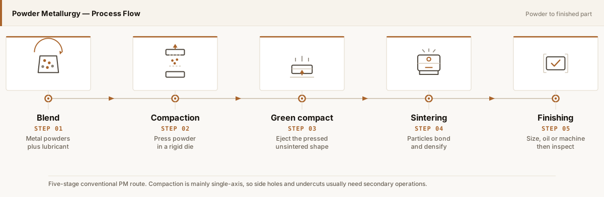
The boundary is direction. Because powder is pressed and ejected along one axis, cross-holes, undercuts and internal threads cannot be formed directly. Where a drawing needs those features, the choice is PM plus machining, or a different process entirely.
7. Metal injection molding
MIM uses fine metal powder compounded with a polymer binder, moulded into a cavity, debound and sintered. Because the material flows as a feedstock rather than being pressed as a powder mass, the geometry constraints of PM largely disappear: side holes, undercuts, thin walls and complex internal detail are all formable in one piece.
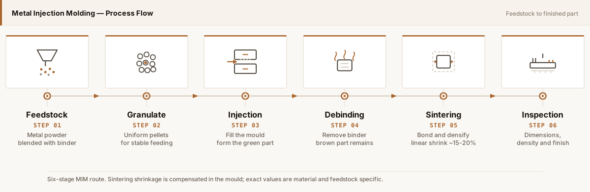
In exchange, MIM brings a 15–20% sintering shrinkage that must be engineered, a mould that costs more than a press die, and a practical size ceiling. It sits between PM and machining: more geometry freedom than PM, lower unit cost than machining at volume, and a hard limit around part mass and wall thickness.
8. CNC machining
Computer-controlled cutting tools remove material from solid stock. Its advantages are breadth rather than speed: almost any metal can be machined, tolerances of ±0.02 mm are routine, and no tooling is required, which makes it the default for prototypes and low-volume work.
The cost structure is the mirror image of a forming route. Unit cost is high because machine time is long and a large share of the raw material becomes chips. As volume rises, a forming route tends to overtake it — unless the geometry is simple enough that machining was never expensive in the first place.
9. Turning
Turning is CNC machining with the workpiece rotating. It is the efficient way to produce round parts: shafts, pins, bushings, sleeves, spacers and threaded components. Modern lathes with bar feeders can run these parts at high rates with tight concentricity.
Its boundary is rotational symmetry. A turned part can have milled features added on a mill-turn platform, but once the majority of the geometry is off-axis, the part is really a machining job rather than a turning job — and if it is also produced in high volume, a forming route deserves a look.
How the decision actually gets made
Experienced buyers do not start by ranking processes. They run three filters in order.
- Geometry filter. Which routes can produce this shape at all? Stampings must start flat, PM must press along one axis, castings need draft and thick enough walls. This usually removes four or five of the nine routes.
- Volume filter. Of what remains, which can justify their tooling at this annual quantity and program life? This removes anything requiring a dedicated die or mould below a few thousand units.
- Requirement filter. Which survivors can hold the critical tolerances, material and surface requirements — alone, or with a defined finishing operation? What is left is a genuine shortlist.
Run in that order, the exercise takes minutes. Run in the wrong order — starting from a preferred process and working backwards — it produces an answer that is defensible in a meeting and wrong on the shop floor.
What to send for a route comparison
A supplier can only compare routes properly with five pieces of information: a 2D drawing with tolerances, a 3D model, the material or its performance requirement, annual volume and program life, and a note on what the part actually does in service. With those, the comparison becomes a costed recommendation rather than a sales pitch.
Process references worth citing. The powder-based routes in this comparison are covered by published standards rather than general practice. ISO 5755:2022 is the current standard for sintered metal material specifications, MPIF Standard 35 publishes material standards for the structural, bearing, powder forged and metal injection moulded product families, and ASTM B883-24 is the standard specification for MIM ferrous materials. For design-side guidance on when each process is appropriate, the EPMA (European Powder Metallurgy Association) publishes industry design and material guidance that sits alongside these standards.
Conclusion
Nine routes, nine boundaries. Casting and forging buy material properties; stamping buys speed on flat parts; machining buys precision and flexibility; 3D printing buys design freedom at low volume; PM and MIM buy geometry at volume.
The useful discipline is to compare complete routes, including finishing operations, against the actual drawing and the actual annual volume. That comparison will sometimes conclude that the part should stay on the machine it is already made on — which is a legitimate outcome, and usually a sign the analysis was honest.
Related component families
These pages move from process comparison to the specific component questions that decide a quotation.
Gears and Transmission
Where PM, MIM, gear cutting and hybrid routes compete around the same function.
Component guide →Mechanism Components
Links, levers, cams and latches where geometry complexity drives the route decision.
Component guide →Cutting and Wear Parts
Parts where hardness and wear resistance narrow the material and process options.
Component guide →Bushings and Structural Parts
Sleeve and flange bushings where press-and-sinter PM usually leads on unit cost.
Component guide →Have a drawing to discuss?
Send it to our engineering team. We review process fit and identify the information needed for a quotation.
Send Drawing for Review