
Locking mechanism
Cams, wedges, balls, latches or drawbar-style parts convert actuator motion into clamping force. These are often the first small complex metal parts worth evaluating.
Automatic tool changers combine locating, locking, load transfer and utility interfaces in a compact assembly. Cams, wedges, latches, pins, bushings, retainers and coupling parts may be worth comparing across MIM, powder metallurgy and machining, but repeatability, contact stress, safety function and service life decide the route.
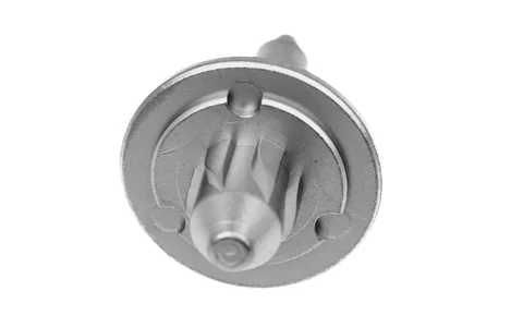
Manufacturing reference: Representative SINTS components are shown to illustrate linkage, shaft and locking-related geometries relevant to tool-changer engineering reviews. Safety functions and final process capability are evaluated against the actual drawing and project requirements.
A tool changer is more than two plates. The manufacturing questions sit in the functions between the robot side and tool side.
Cams, wedges, balls, latches or drawbar-style parts convert actuator motion into clamping force. These are often the first small complex metal parts worth evaluating.
Pins, bushings, tapered seats and datum faces establish repeatable position. They usually put a premium on hardness, roundness, finish and stable machining datums.
The interface must transmit payload and moment without excessive deflection or wear. Large structural plates are usually not MIM candidates; compact internal mechanisms may be.
Pneumatic, electrical or fluid modules can add sleeves, valve-like inserts, retainers and compact stainless parts. Sealing and corrosion requirements can dominate process choice.
The table is an initial screening tool. Lock integrity, safety factors, locating repeatability and wear life must be confirmed on the actual design.
| Component | Function | First route to evaluate | Why / watchout |
|---|---|---|---|
| Locking cam / wedge | Generates or retains clamping force | MIM — high potential | Compact 3D geometry can favor MIM; contact stress, hard surfaces and safety margins require validation. |
| Latch / pawl / lever | Locks, releases or confirms position | MIM — often worth evaluating | Good fit when small and complex at repeat volume; pivot wear and fatigue can drive finishing. |
| Locating pin / bushing | Defines repeatable alignment | CNC / turning / grinding | Simple rotational geometry and tight locating surfaces often favor direct machining or grinding. |
| Coupling ring / compact carrier | Transfers motion or supports internal mechanism | MIM + machining, PM or CNC | Depends on geometry, pressing direction, wall section and which datums must remain machined. |
| Small gear / rack feature | Synchronizes or actuates locking movement | PM / MIM / gear process | Tooth quality, backlash, density and wear determine whether near-net-shape teeth are sufficient. |
| Spring seat / retainer | Retains springs, balls or compact actuator elements | MIM / PM / CNC | Often simple, but integrated features or volume can change the economics. |
| Master / tool plate | Main robot-side and tool-side structure | CNC / aluminum process | Large plate geometry, flatness and interface features normally make CNC or other structural processes the natural route. |
These real SINTS components illustrate compact motion, linkage and shaft geometries relevant to process-selection discussions. Final suitability is evaluated from the actual drawing and functional requirements.
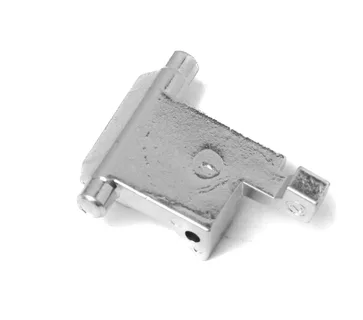
Useful when discussing compact force-transfer parts, latch-like geometry, pivot features and integrated bosses.
SINTS manufacturing referenceUseful for discussing rotational interfaces, locating-adjacent features and where turning, grinding or selective machining may remain necessary.
SINTS manufacturing referenceUse this application guide for locking, locating, load and utility context. Use Product family pages for the component-level manufacturing decision.
Cams, wedges, latches, levers, retainers and locking elements.
Product family →Locating pins, spindles and moving interfaces where fit and secondary control matter.
Product family →Bearing and locating interfaces where compaction, density and sizing are relevant.
Product family →Small gear or rack features where tooth quality, backlash and wear drive the route.
Product family →Utility-transfer sleeves, valve-adjacent inserts and sealing interfaces when pneumatic or fluid modules are involved.
Product family →The component is small, three-dimensional, feature-rich and repeated at enough volume that several machining setups or assembled sub-features may be consolidated.
The component is press-compatible, repeated at high volume, and suited to near-net-shape structural, gear or bushing production.
The component is a large plate, low-volume item, locating pin/bushing, prototype, or dominated by tight datums, flatness and precision contact surfaces.
Include datum structure, mating interfaces and any already-defined finishing operations.
State the material, heat-treatment condition and corrosion requirement if already fixed.
MIM and PM economics depend strongly on stable repeat demand and tooling amortization.
Share the load path and function of the component rather than only the nominal part weight.
Locking, locating and sliding parts are judged differently from static retainers.
Identify the surfaces that establish robot-to-tool position so they are not treated like ordinary dimensions.
Robot tool changers join an end effector to an arm through a locking and locating interface. These answers cover the locking chain, repeatability questions and the component scope a tool-changer review should cover.
Small complex locking cams, wedges, latches, levers, retainers and compact actuator components are often worth evaluating first. Final suitability depends on load, safety function, wear, tolerance, material and annual volume.
Usually they are not the first MIM target. Simple rotational geometry, tight roundness and precision locating surfaces often make turning, CNC machining and grinding more direct.
Potentially, especially for repeat-volume structural, bushing or gear-like parts whose geometry is compatible with compaction. Density, strength, tooth quality and finishing requirements must still be checked.
SINTS can support process selection and manufacturability review. Final safety, fatigue, load retention and failure-mode validation belong to the project-specific engineering and qualification process.
It covers the metal parts in the locking and locating chain — locating pins and bushings, locking balls or pawls, cam and wedge parts, levers, springs, retainers and the small structural components that carry the payload. The family sits between the arm flange and the tool, so repeatability and interface condition matter more than absolute strength, and the parts are typically small, loaded in shear and present in repeat volume.
Repeatability is a system property that each interface part either supports or erodes. Locating features set the datum position, the locking chain holds it under load and any wear, clearance or deformation in those parts appears as tool-tip deviation. That means hardness, surface condition, contact geometry and wear allowance become design inputs rather than afterthoughts, and a part can be dimensionally correct yet still unsuitable if its contact surfaces are not controlled.
Both can be evaluated for repeat-volume locking and locating parts where the geometry has enough complexity to justify near-net shaping — bushings, cam profiles, wedge parts and carriers with integrated features. Density, hardness, contact-load capacity and wear behaviour then have to be reviewed against the locking load, and any part whose function is load-holding is assessed on its measured properties, not on the process name.
SINTS reviews manufacturability: whether a component can be produced to the stated geometry, material and volume, which process route fits and which features need secondary operations. SINTS does not certify, validate or approve the safety of a locking mechanism, and does not substitute for the customer's own load testing and risk assessment. Separating the manufacturing review from the safety case keeps both useful.
We can review geometry, material, volume, critical datums and likely secondary operations — including cases where keeping the part CNC-machined is the better answer.