
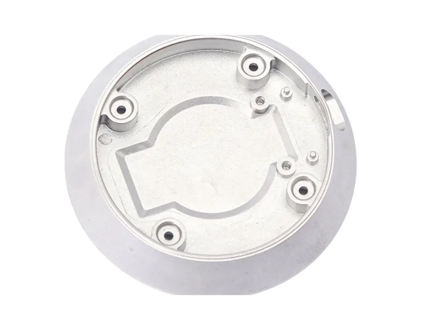
What pneumatic actuator supports locate within the mechanism
Review this component together with its mating parts and delivered condition. The interfaces below define the drawing information needed to assess forming, finishing and inspection.
The available reference is support-body geometry, not proof of a complete gripper or pneumatic cylinder.
Supporting part, guide arrangement and mounting-pattern interfaces
Identify the exact supporting part, guide arrangement and mounting pattern.
Specify moving-member clearance and any interfaces that have a separate sealing role.
Why distinguish supporting and sealing interfaces?
A supporting face locates a member, while a sealing surface has a different role and acceptance requirement.
Both may exist in a pneumatic assembly without being interchangeable.
Identifying the actual function prevents pressure-related assumptions from being applied to unrelated support geometry.
Machining versus near-net forming for support geometry
Compare machining and near-net forming for the support geometry.
Critical bores, seats or mounting surfaces may need final machining according to the actual assembly.
The proposed route is confirmed for your drawing, material and quantity. An image does not establish a fixed tolerance or a complete process specification.
Compare manufacturing capabilities →Support component material, wear treatment and environment requirements
Define material and final treatment against load direction, wear and the operating environment.
Mark surfaces whose fit or contact changes after finishing.
Rated loads, pressure limits and operating life require their own agreed design and acceptance requirements.
Review material-selection information →Mounting, guide alignment and non-interference checks
Check mounting, guide alignment and movement without interference.
Any pneumatic sealing or operating requirement must be defined for the relevant interfaces.
Specify the drawing revision and the condition in which each dimension is inspected. Record the agreed dimensional and functional checks before sample approval.
Quality documentation →Prepare a Product-Specific RFQ
- Component definition. Send the 2D drawing and 3D model, where available, with the drawing revision and the requested part or assembly scope.
- Mating information. Include the assembly references needed to define the interfaces discussed above.
- Delivered condition. State material, finishing and inspection requirements, identifying any items that need a manufacturing recommendation.
- Supply plan. Include sample needs, expected order and annual quantities, packaging requirements and target timing.
Product Questions
Does a support-body reference include pneumatic sealing performance?
No. Define which surfaces seal and provide their requirements; a mechanical support image does not establish leakage performance.
Why distinguish supporting and sealing interfaces?
A supporting face locates a member, while a sealing surface has a different role and acceptance requirement. Both may exist in a pneumatic assembly without being interchangeable. Identifying the actual function prevents pressure-related assumptions from being applied to unrelated support geometry.
How should the part be checked in the tool or mechanism?
Check mounting, guide alignment and movement without interference. Any pneumatic sealing or operating requirement must be defined for the relevant interfaces.
Technical Context
The product-specific notes above identify drawing-review questions. General process and material references are collected separately; they do not verify a material grade, production qualification or performance claim for the pictured part.
Manufacturing and material references →