
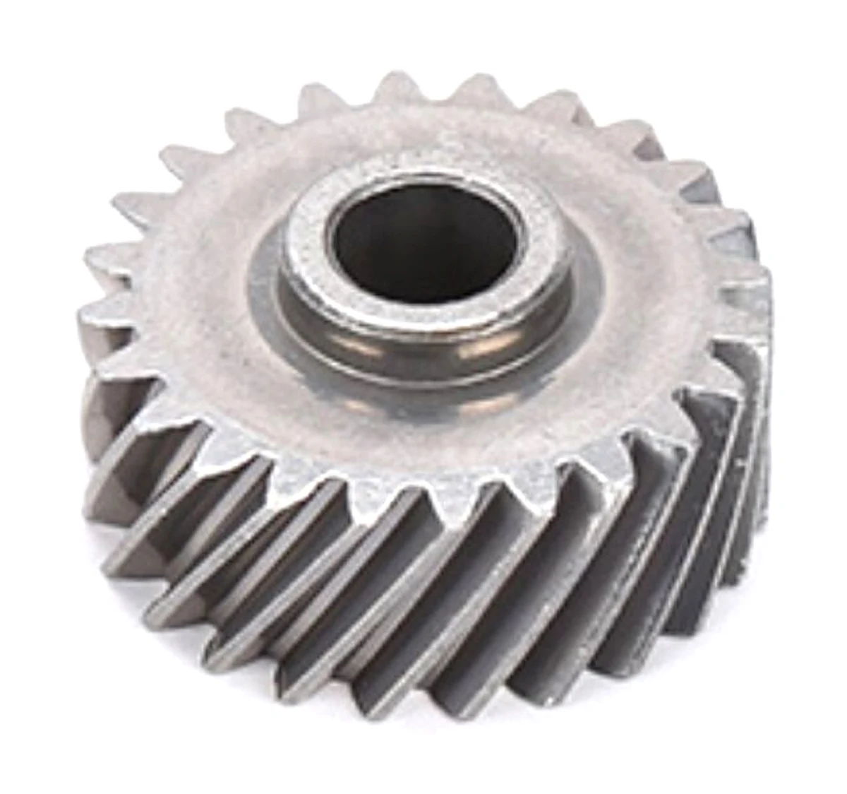
What helical gears require beyond a straight-gear convention
Review this component together with its mating parts and delivered condition. The interfaces below define the drawing information needed to assess forming, finishing and inspection.
The drawing must define the helix as well as the mounting features and mating arrangement.
Helix angle, hand and tooth-parameter interfaces
Specify helix angle and hand, tooth count, pressure angle and the convention used for module or pitch.
Include face width, bore fit and the mating gear.
Why state helix hand together with angle?
Angle alone does not describe the complete direction of a helical tooth form.
A clear drawing identifies both direction and parameter convention, then relates them to the mating gear.
This avoids treating superficially similar gears as a defined interchangeable pair.
Gear machining versus forming for helix geometry
Compare gear machining and feasible forming routes for the helix and production quantity.
Tool access, release and any tooth finishing require a specific review rather than a straight-gear assumption.
The proposed route is confirmed for your drawing, material and quantity. An image does not establish a fixed tolerance or a complete process specification.
Compare manufacturing capabilities →Helical gear material, density and treatment requirements
Material and final condition must be reviewed against the defined load, wear, lubrication and environment.
Where powder processing is proposed, agree any relevant density and treatment requirements.
A material family or hardness value alone does not specify the gear or bearing duty.
Review material-selection information →Tooth geometry, mounting datum and backlash checks
Check tooth geometry, mounting datums and the agreed backlash or contact.
Include operating load, speed and assembly conditions in sample approval.
Specify the drawing revision and the condition in which each dimension is inspected. Record the agreed dimensional and functional checks before sample approval.
Quality documentation →Prepare a Product-Specific RFQ
- Component definition. Send the 2D drawing and 3D model, where available, with the drawing revision and the requested part or assembly scope.
- Mating information. Include the assembly references needed to define the interfaces discussed above.
- Delivered condition. State material, finishing and inspection requirements, identifying any items that need a manufacturing recommendation.
- Supply plan. Include sample needs, expected order and annual quantities, packaging requirements and target timing.
Product Questions
Why must the drawing state the parameter convention for module or pitch?
Different reference planes can describe helical teeth; an explicit convention avoids mismatched interpretation with the mating gear.
Why state helix hand together with angle?
Angle alone does not describe the complete direction of a helical tooth form. A clear drawing identifies both direction and parameter convention, then relates them to the mating gear. This avoids treating superficially similar gears as a defined interchangeable pair.
Which checks should be included in gear or support approval?
Check tooth geometry, mounting datums and the agreed backlash or contact. Include operating load, speed and assembly conditions in sample approval.
Technical Context
The product-specific notes above identify drawing-review questions. General process and material references are collected separately; they do not verify a material grade, production qualification or performance claim for the pictured part.
Manufacturing and material references →Helical gear reference library
Component reference and drawing inputs
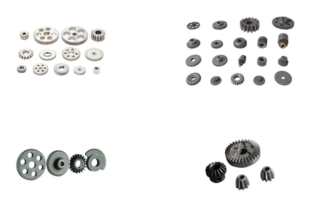
Mixed gear references for tooth-form review
The photo illustrates geometry. Final tooth form, grade, dimensions and condition are defined in the drawing.
Discuss a similar component →Representative custom component references. Dimensions, material, manufacturing route and validation requirements are confirmed from your drawing; these are not off-the-shelf catalog items.
Application, manufacturing and RFQ review
Use these points to prepare a review of a similar component. The illustration does not define a standard supply specification.
- Define helix angle and hand with the tooth data and mating gear information.
- Explain shaft location, axial restraint and the assembly references used for inspection.
- Review compaction and finishing feasibility from the actual geometry; do not assume the route from the product name.
Related guide: Sintered Gear Secondary Operations: Sizing, Machining and Heat Treatment
Submit your drawing for a manufacturing-route review →