
The customer, drawing number and all commercial figures have been withheld. Dimensions and material below are as stated on the drawing; the route comments are SINTS engineering assessment for this part.
The part, as drawn
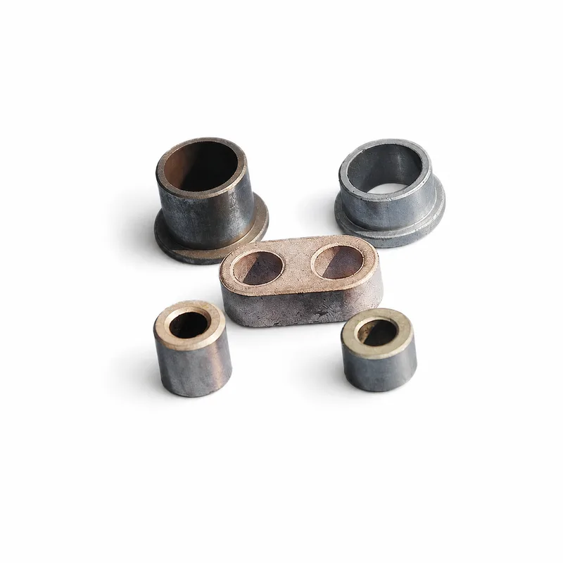
It is a flanged bushing used as an anti-loosening threaded insert in an automotive assembly: a Ø26 mm flange, a short undercut, and an M18×1 external thread on a body that carries a slot straight through it. The lengths close exactly — flange 1.5 mm, undercut 0.50 mm and thread 7.50 mm add up to the 9.50 mm overall length — and the slot closes too: an arc-centre distance of 6.5 mm plus two 3.5 mm radii gives the stated 13.5 mm overall slot length. That consistency matters, because a drawing that does not close cannot be quoted from.
| Feature | As drawn | What it means for a PM route |
|---|---|---|
| Material | AISI 304 | Within the documented PM stainless range. 316L is the usual upgrade where chloride exposure is expected, at higher feedstock cost. |
| Mass | 17.67 g | Drives material cost directly. Our geometry recomputation came out 5–15% lower, so the STEP file was requested before the material figure was locked. |
| Overall length | 9.50 mm | Flange 1.5 + undercut 0.50 + thread 7.50. Pressable in one direction. |
| Flange | Ø26 ±0.1 × 1.5 mm | Thin flange against a heavier body: uneven mass distribution, so density follows the compaction design rather than the alloy. |
| Undercut | 0.50 mm below the flange | Root diameter was not dimensioned. It sets pressed volume, and volume sets material cost. |
| External thread | M18×1, 7.50 mm long | Not pressed. Formed after sintering by thread rolling, or cut by turning if density or class rules rolling out. |
| Cross slot | 7.0 mm wide (2 × R3.5 ±0.1), arc centres 6.5 ±0.1, overall 13.5 mm | Pressed in the compaction direction. The two ±0.1 values are the features that add sizing. |
| General tolerance | ISO 2768-mK | Reasonable basis for a sintered part; the three ±0.1 features are called out individually on top of it. |
| Edge condition | No sharp or irregular edges; all edges rounded | Tumbling or vibratory finishing becomes a mandatory operation, not an option. |
| Annual volume | 73,560 pcs | What makes the tooling amortise. Volume is the reason this is a PM question at all. |
Why density decides the route
The reference density for sintered 304 is 7.6–7.8 g/cm³, so a target of ≥7.0 g/cm³ is not a stretch for the material in the abstract. The risk is specific to the part. A 1.5 mm flange, a 0.50 mm undercut and a 7 mm slot leave the section mass deliberately uneven, and in press-and-sinter density follows mass distribution: thin sections and slot edges are where it drops first.
That matters because a rolled thread is a forming operation, not a cutting one. The thread is displaced from the material already there, so the material has to be dense enough to flow into the flank without tearing or leaving it partially filled. On this part SINTS set ≥7.0 g/cm³ as the threshold at which rolling stays the route. If measured density comes in below it on the trial parts, the thread moves to turning — and turning an M18×1 on a 304 sintered blank costs several times what rolling does, per piece, on every piece.
So the density requirement is not a material footnote. It sits upstream of the thread, the thread sits upstream of the finishing sequence, and the finishing sequence is where most of the piece price lives on a part this small. It was written on the drawing and agreed before tooling rather than discovered at first article.
The three callouts that changed the route or the price
Eight points were raised against the drawing. Three of them could not be left to interpretation, because each one changes either the process or the piece price.
| Point | What was missing | Why it decides something |
|---|---|---|
| Thread accuracy class | The M18×1 thread carried no class (6g or 6h) | Class tolerance decides whether rolling can hold the requirement or the thread has to be cut. Rolled and turned threads are far enough apart in cost to move the quotation, not just the process note. |
| Undercut root diameter | The 0.50 mm undercut had no root diameter | Root diameter sets the pressed volume. Without it the mass calculation is an estimate, and the material line item is an estimate with it. |
| Slot position datum | The cross slot had ±0.1 mm size tolerances but no position or symmetry datum | Without a datum the inspection method is undefined. That is a gauge and operation cost, and it is also the difference between a part that passes first article and one that argues about it. |
The other five
These did not change the route, but they had to be closed for the quotation to mean anything.
| Point | What was missing | Effect |
|---|---|---|
| Slot dimension logic | 6.5 ±0.1 mm and R3.5 ±0.1 mm appear together | Read as arc-centre distance plus radius, the values reconcile to the stated 13.5 mm slot length. Confirmed rather than assumed, because the alternative reading changes the pressed slot. |
| Density, hardness, tensile, torque | None stated | The four fields that define a PM part. Hardness and density cannot be inherited from bar stock the way they are on a machined part. |
| Corrosion requirement | No salt-spray hours, no surface treatment called out | Decides whether passivation and impregnation are in scope, and to what acceptance level. |
| Surface roughness and edge radii | Rounded edges requested in a note, but no Ra and no radii values | Drives finishing time and how the edge requirement is inspected. |
| Mass verification | 17.67 g on the drawing against 15–17 g from our own recomputation | A 5–15% spread on mass is a 5–15% spread on material cost at 73,560 pieces. STEP file requested before the price was fixed. |
Why impregnation is proposed rather than assumed
Sintered stainless at this density retains a small amount of connected porosity. On a part whose function is a threaded joint, that porosity is not a cosmetic issue: moisture can sit in the thread root and in the slot flanks and start the corrosion path from inside the material. Vacuum impregnation seals the surface-connected pores and is the normal answer for a threaded PM part that will see humidity.
It is written as a proposal, not a default, because it conflicts with one customer requirement: an impregnated part is an oiled part. If the assembly needs dry, clean components, the answer is a different sealing route or a different density — either way it changes the part, so the customer has to choose it, not inherit it.
What was quoted, and what the quotation does not promise
The quotation covered the route as it stands: compaction and sintering to near-net shape, thread rolling after sintering conditional on measured density of 7.0 g/cm³ or above, deburring and vibratory finishing to meet the edge requirement, then passivation and vacuum impregnation subject to the salt-spray level still to be confirmed. Tooling and first samples were scheduled at 25–30 days for tooling plus 7–10 days for samples after tooling approval, quoted for this part and not offered as a standard lead time.
What the quotation does not contain is a price per piece in public, a yield figure, or a delivery record. This is a live evaluation of a real drawing, not a completed production program. The dimensions, the material and the volume are the customer's; the engineering commentary is ours.
Two things this note is not. It is not a claim that PM has replaced another process for this part — the route was being evaluated, and a machined alternative remained on the table until density and thread class were settled. And it is not a material qualification: the reference values for sintered 304 come from the SINTS material reference data, while the acceptance values for this part belong to this drawing and are confirmed through the agreed sample and inspection plan.
What to send for a review like this
Four things decide most of the answer: the 3D model, the material and its final condition, the annual volume, and the features that must not move. The 2D drawing adds the tolerances, the datums and the edge requirements. If the drawing was written for machining, expect a short list of questions back — on a PM route, density, hardness and surface condition are process decisions, and every one of them has a price attached.