
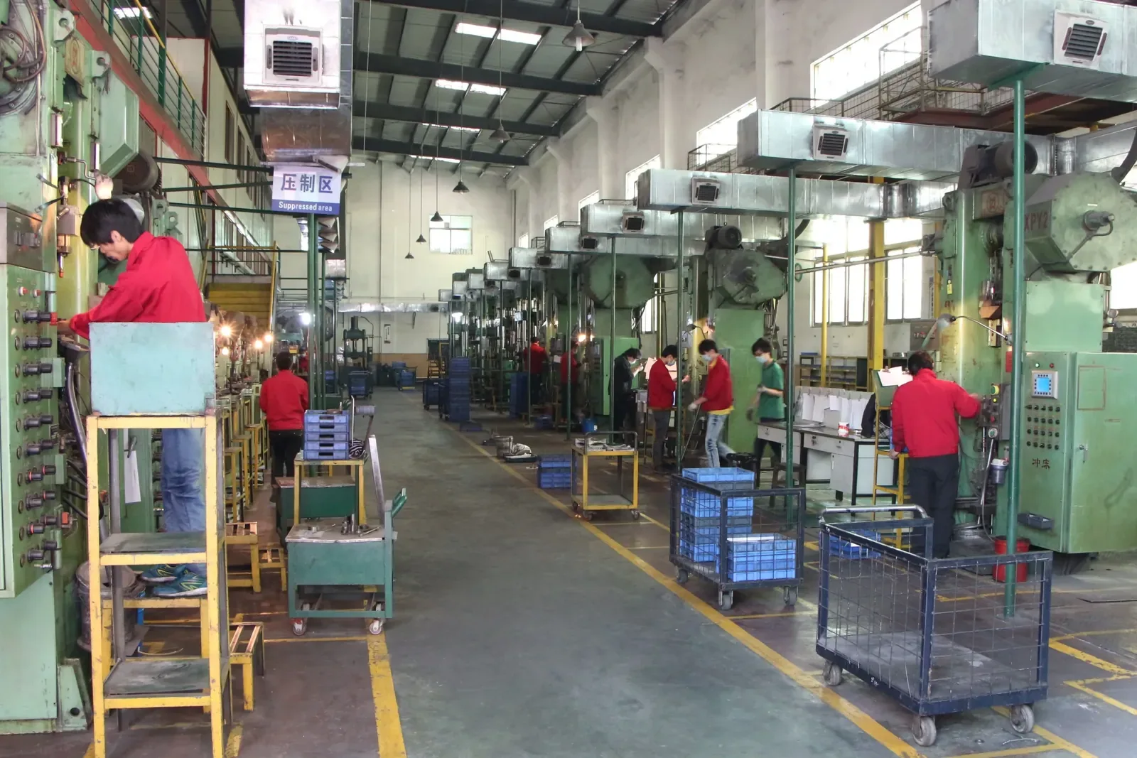
Powder metallurgy (PM) is the older and, at volume, the cheaper cousin of metal injection molding. Metal powder is blended with a lubricant, pressed into shape in a rigid die, and sintered in a furnace so the particles bond into a solid component. No melting, almost no scrap, and cycle times measured in seconds per part.
The trade-off is geometry. Compaction happens along a single axis, so undercuts, cross-holes and complex three-dimensional shapes are difficult or impossible to press directly. Understanding that one constraint explains almost everything about which parts belong in PM and which do not.
What powder metallurgy means
Powder metallurgy is a family of processes that start with metal in powder form and consolidate it below the melting point. The most common variant by far is press-and-sinter: blend, compact in a die, sinter. Other members of the family include metal injection molding, hot isostatic pressing and additive manufacturing — all of which are, technically, powder metallurgy.
In everyday commercial use, "PM" means press-and-sinter. The powder is blended with a small amount of lubricant to reduce friction during ejection, pressed at high pressure into a die cavity, and then heated in a controlled-atmosphere furnace. At sintering temperature the particles weld together by diffusion, the lubricant burns off, and the compact becomes a single coherent metal part.
The process has been in industrial use for roughly a century, and its economics are well understood: high tooling cost, very low unit cost, and a geometry envelope set firmly by the direction of pressing.
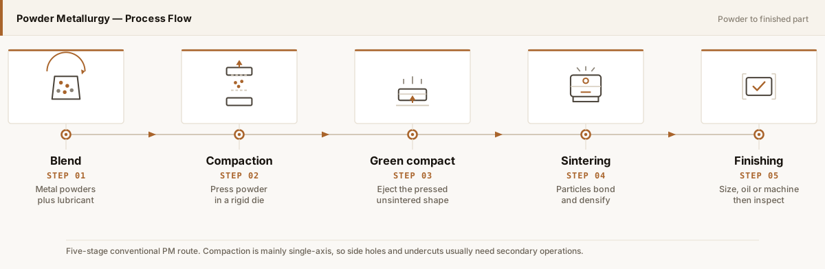
The five stages
1. Powder blending
Elemental or pre-alloyed powders are mixed with a lubricant and, where required, with graphite or alloying additions. The blend determines the final composition. Typical iron-based powders sit in the 20–150 µm range — substantially coarser than MIM feedstock, which is a direct consequence of the need to flow into a die under pressure rather than a fine mould cavity.
2. Compaction
The blended powder fills a die cavity and is pressed between upper and lower punches, usually at 400–800 MPa. The green compact that results has the intended outline, a density of roughly 85–90% of theoretical, and enough handling strength to survive transfer to the furnace. This is the shaping step, and it is where the geometry limits are set.
3. Green compact handling
The pressed part is ejected and transferred without sintering. It is fragile relative to a finished part, and any feature that would break during ejection — a very thin wall, a sharp unsupported edge — has to be redesigned. Many "PM cannot make this" conclusions are really ejection problems rather than pressing problems.
4. Sintering
Sintering takes place in a belt or batch furnace, typically between 1,100 °C and 1,300 °C for iron and steel grades, in a reducing or inert atmosphere. Particles bond by diffusion, density rises to the 6.8–7.2 g/cm³ range for iron-based materials, and the part gains its mechanical strength. Linear shrinkage during sintering is much smaller than in MIM — on the order of 0.5% to 2% for many grades — because the compact already starts dense.
5. Finishing
Common finishing steps include sizing to improve dimensional accuracy, machining of features that cannot be pressed, steam treatment for wear and corrosion resistance, oil impregnation for self-lubricating bearings, and plating or coating. Sizing is particularly useful: it corrects small dimensional variation without removing material.
Porosity is a design variable in PM, not automatically a defect. Sintered bearings rely on interconnected porosity to hold lubricating oil. Structural parts usually want density as high as the grade allows. Telling the supplier which one you need changes the process route, so state the application, not just the drawing.
Why compaction direction decides geometry
Because pressure is applied along a single axis, material must be able to flow and be ejected along that axis. That single constraint produces a fairly clear list of what PM can and cannot do.
| Feature | Press-and-sinter PM | Comment |
|---|---|---|
| Through-holes, parallel to pressing | Straightforward | Formed by a core rod in the die |
| Stepped diameters, splines, keyways | Straightforward | Produced by punch and die steps |
| External profiles and gear teeth | Straightforward | A core strength of PM — gears are a flagship application |
| Cross-holes and side holes | Not directly pressable | Added by secondary machining, or the part moves to MIM |
| Undercuts and reverse tapers | Not directly pressable | Requires split dies or machining — usually uneconomical |
| Internal threads | Not pressable | Machined after sintering, or formed as a plain bore |
| Large flat faces | Fine | Watch for density gradients on long thin parts |
Density, tolerance and strength
PM parts are graded by density, and density drives mechanical properties more than any other variable. An iron-based part at 6.8 g/cm³ and one at 7.2 g/cm³ may carry the same nominal material designation and behave very differently in fatigue and impact. When specifying a PM part, ask for the required density rather than assuming the material name settles it.
On tolerance, PM is genuinely strong in the pressing direction. Dimensions formed by the die — outer profiles, hole diameters — are repeatable to within roughly ±0.05 mm on small features. The direction of pressing, meaning the part height, is the weaker axis because it depends on fill depth and powder compressibility. Tolerances of ±0.1 mm or so are common there, and tighter requirements generally call for sizing or machining.
A practical consequence: it is often cheaper to press a PM part and machine one critical face than to try to press the whole part to final tolerance. Hybrid routes are normal, not a compromise.
Advantages and limitations
Advantages
- Very low unit cost at volume. Pressing cycles are short and material utilisation is close to 100%.
- Near-net-shape with minimal scrap. There is no machining stock to remove and no chip stream to manage.
- Good dimensional repeatability. Die-formed features hold tolerance consistently across a production run.
- Controllable porosity. Useful for bearings, filters and parts that must hold oil or damp vibration.
- Broad material range. Iron, low-alloy steel, stainless steel, copper, brass, bronze, nickel and various magnetic alloys.
Limitations
- Single-axis geometry. The defining constraint, discussed above.
- Tooling cost. A die set is a real investment and dominates the decision at lower volumes.
- Part size and press capacity. Press capacity caps the footprint and the required compaction pressure.
- Density gradients on long parts. Tall parts fill unevenly, so density and properties vary with height.
- Thin walls are difficult. Very thin sections may not survive ejection or may fill poorly.
PM or MIM?
This is the question buyers ask most often, and the answer is usually driven by geometry rather than cost. If the part can be pressed — meaning the features run along the pressing axis — PM will normally be the cheaper route because the powder is coarser, the binder is simpler and the shrinkage is far smaller. If the part needs side holes, undercuts and three-dimensional detail, PM cannot press it in one piece consistently.
| Factor | Press-and-sinter PM | MIM |
|---|---|---|
| Geometry | Single-axis pressing | Three-dimensional, side holes, undercuts |
| Sintering shrinkage | About 0.5–2% | Typically 15–20% |
| Typical density | 6.8–7.2 g/cm³ (iron-based) | 95–99% of theoretical density |
| Wall sections | Limited; thin walls risk ejection damage | About 1–3 mm works well |
| Unit cost at volume | Usually the lowest of the two | Higher, but replaces more machining |
| Best-fit parts | Gears, bushings, rotors, levers, plates | Small complex housings, cams, lock parts, surgical jaws |
Where PM fits in SINTS programs
SINTS operates press-and-sinter powder metallurgy alongside MIM. PM is normally proposed for high-volume parts whose geometry runs along the pressing axis: gears, bushings, rotors and structural components. Where a part needs cross-holes or complex three-dimensional detail, the useful question is whether PM plus a machining step beats MIM outright — and that is a cost calculation on the actual drawing, not a preference.
Gears and Transmission
Sintered gears, sprockets and transmission parts pressed to near-net shape at volume.
Component guide →Bushings and Bearings
Sleeve and flange bushings, including oil-impregnated types where porosity is designed in.
Component guide →Structural Components
Levers, plates, links and brackets where density and tolerance are specified together.
Component guide →Precision Small Components
Small pressed parts where repeat volume supports a dedicated die set.
Component guide →Related component families
Use these pages to move from process theory to the specific component questions that affect a quotation.
Conclusion
Powder metallurgy is one of the most cost-effective ways to make a metal part in volume, provided the geometry respects single-axis pressing. It delivers near-net shapes, tight dimensional repeatability and almost no material waste, at a unit cost that machining rarely matches.
Its limit is design freedom in the third dimension. When a drawing needs cross-holes, undercuts or complex internal detail, the realistic options are PM plus machining, or MIM. Choosing between those two is a straightforward comparison once the drawing, the annual volume and the critical tolerances are on the table.
Have a drawing to discuss?
Send it to our engineering team. We review process fit and identify the information needed for a quotation.
Send Drawing for Review